

Article Figures & Data
Figures
- FIGURE 1
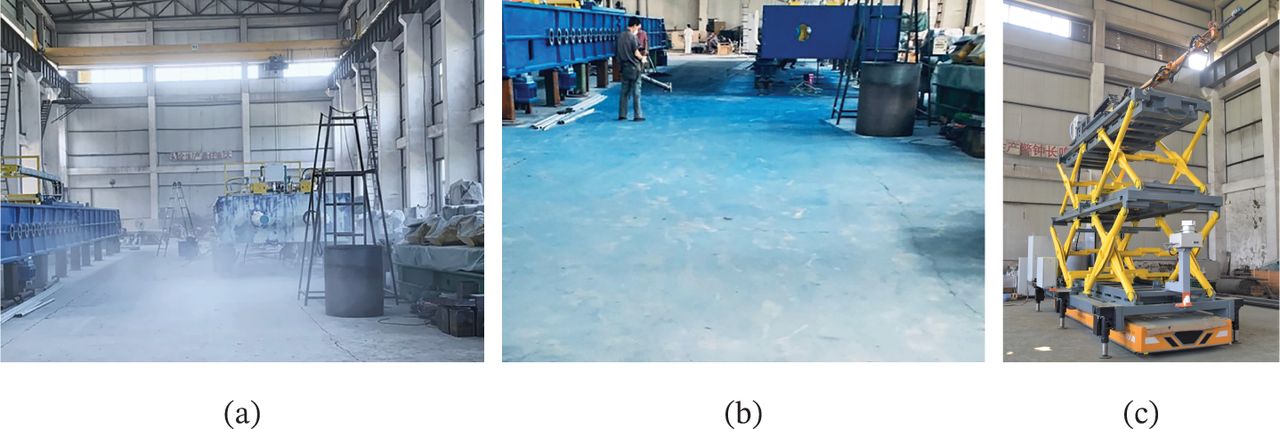
(a) The factory is always dusty during manufacturing; (b) The ground will be stained with paint after spraying; and (c) The mobile spraying system. An 8-m-long robotic arm was set on an 5-m-long AGV. It required high angle accuracy for spraying.
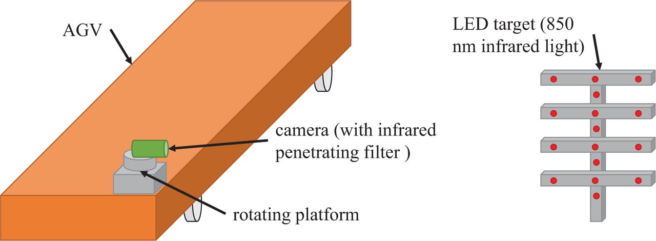
- FIGURE 2
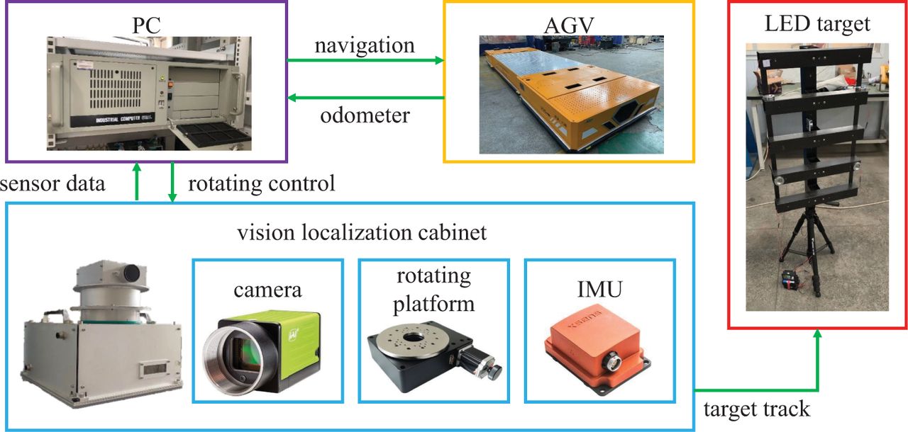
Overview of the experimental AGV navigation system; the length and width of the AGV are 5 and 1.8 m, respectively. The camera located before the AGV and the LED target should be 3.5~10 m away from the camera. An infrared penetrating filter is mounted on the camera lens. Distributed LED lights are placed on the target; they emit infrared light of 850 nm. The camera will track the LED target through rotations. Thus, the pose of the AGV with full view of the LED target can be computed.
- FIGURE 3
Structure of localization system: A navigation personal computer (PC) was connected with sensors and AGV to run the positioning system. The rotating platform and camera formed a feedback servo tracking system that maintained the LED target in the middle of the camera view. The camera transferred the LED target image to the PC to compute the vision pose. An IMU was installed in the vision localization cabinet to improve vision results. The AGV then sends the odometer data to the PC and receives control instructions.
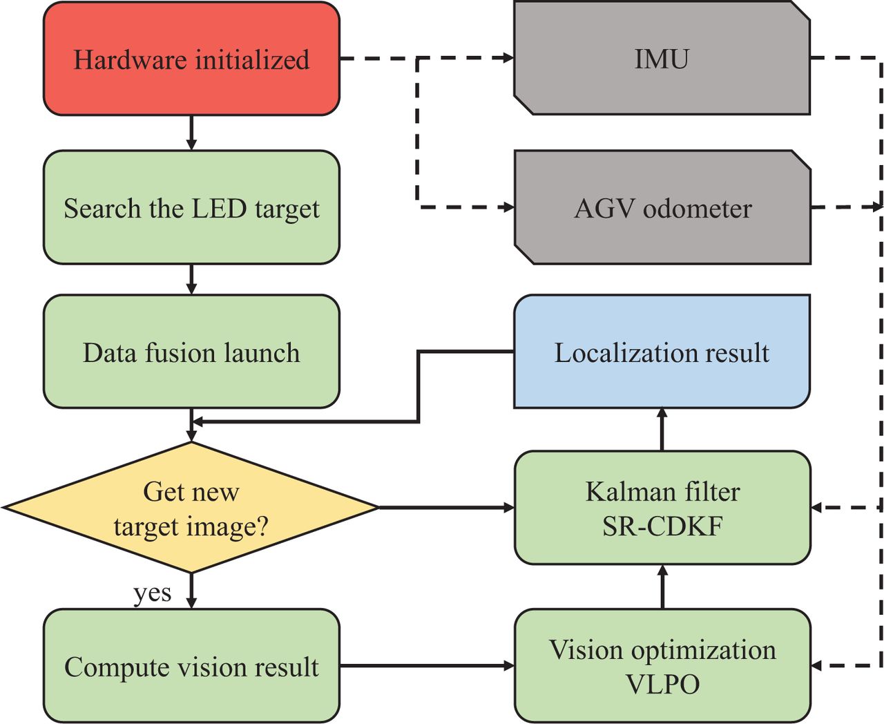
- FIGURE 4
Flowchart of the localization system: The camera searches the LED target after system initialization and continues to track the target. When the camera obtains a new valid image, including the full target, a vision computation thread is used to handle the image and optimize results. Then, the vision observation results are sent to the Kalman filter process with the IMU and odometer data. The filtering process estimates the final AGV pose for navigation. If there is no new image in the data fusion loops, the odometer and IMU are used to predict the pose.
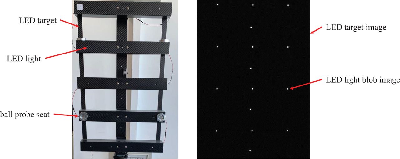
- FIGURE 5
LED light target (left) and its image captured by the camera (right); the LED lights fixed on the bracket are non-coplanar. There are five ball probe seats on the target that can hold the laser tracker target ball while the camera is set to dark mode and has an infrared penetrating filter. Thus, we can only see the white LED light blobs.
- FIGURE 6
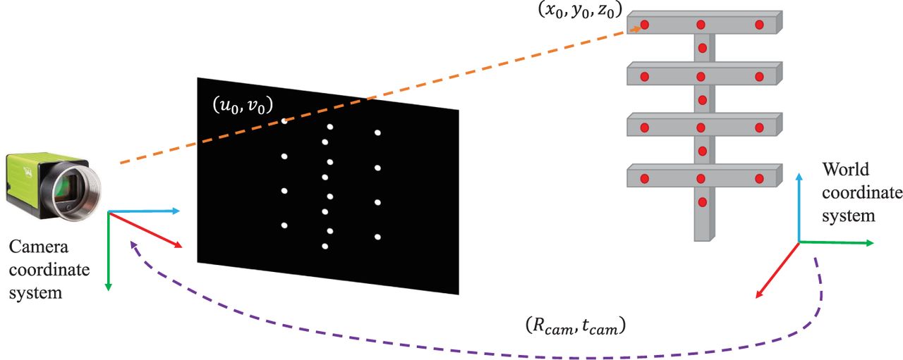
The camera captures the LED light target and recognizes the white blobs in its image. The blobs are sorted by height to match the real LED lights. (u0, v0) is the 2D point coordinate of the first blob in the image plane. (x0, y0, z0) is the 3D point coordinate of the first LED light in the world coordinate system defined by the laser tracker. The camera pose in the world frame is the transformation (Rcam, tcam), which can be computed through the ePnP algorithm.
- FIGURE 7
This is an illustration of a calibration experiment that transfers the camera pose to the rotating center. Two calibrated LED targets are fixed on the ground while the AGV remains still in the middle. We rotate the platform to ensure that the camera views each target and computes the vision results.
- FIGURE 8
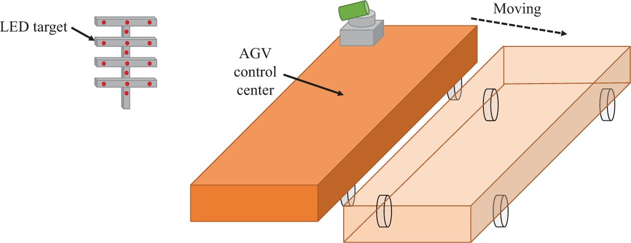
This is a depiction of a calibration experiment that transfers the camera rotating center to the AGV control center. Calibrated LED targets are fixed to the ground and the AGV stays at different stations.
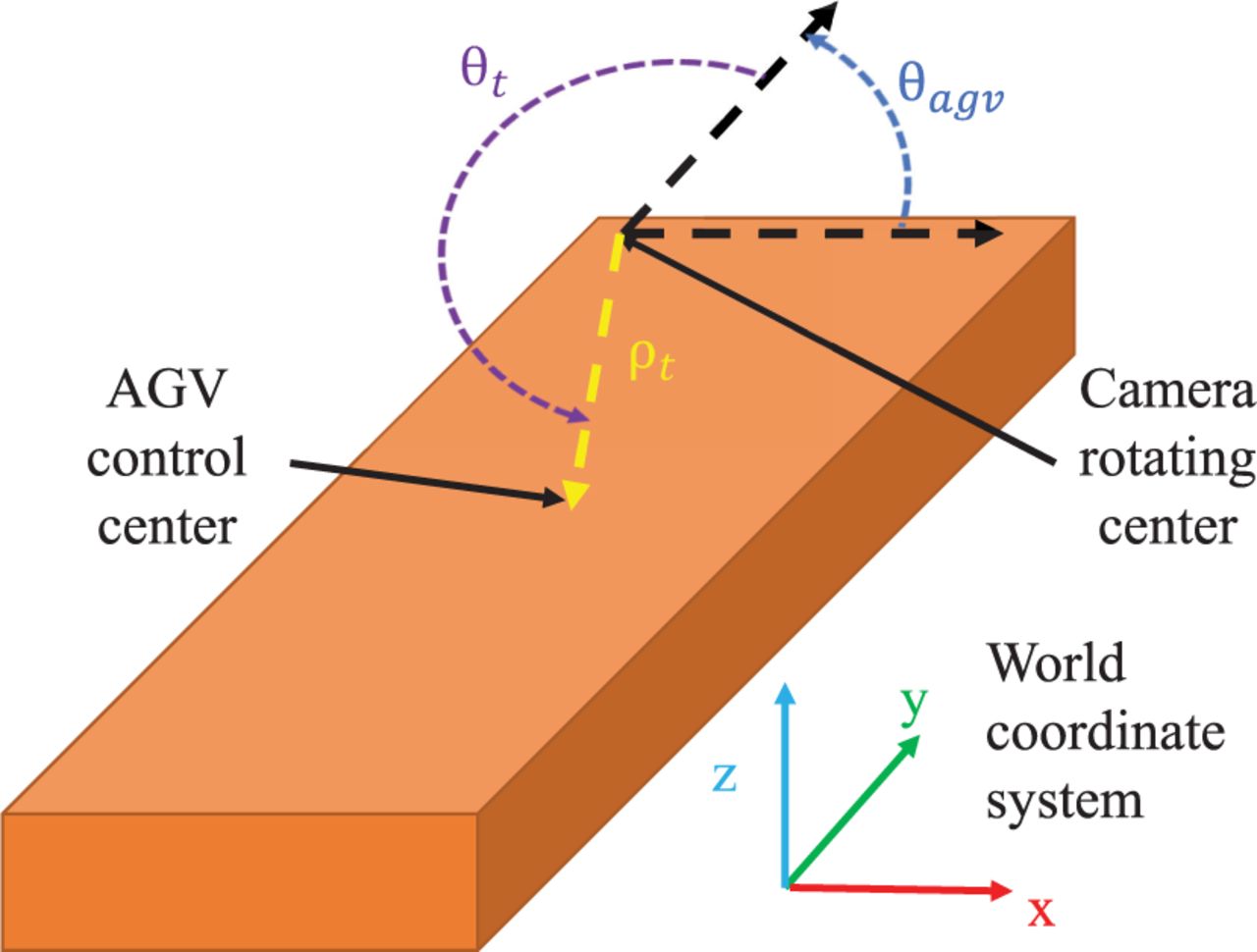
- FIGURE 9
Position transformation between the camera rotating center and AGV control center
- FIGURE 10
LED blob image when the stationary camera is watching the target; the LED blob has pixel-level vibrations, which generate vision noise at a position and yaw angle of 2 mm and 0.02°, respectively.
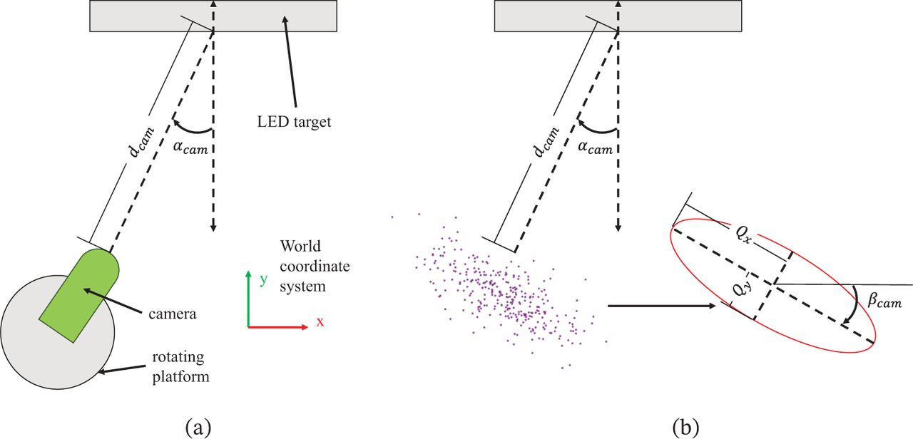
- FIGURE 11
(a) Top view of the camera and LED target in which dcam is the distance between them and αcam is their intersection angle; (b) Purple dots denote the vision pose results of the camera rotating center. The dots approximately obey the Gaussian distribution and can be simplified as the red ellipse. Qx is the semi-major, Qy is the semi-minor, and βcam is the rotating angle.
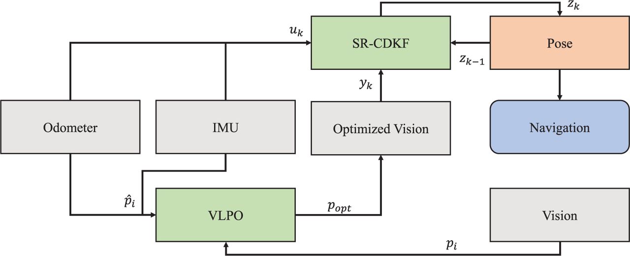
- FIGURE 12
This is the structure of data fusion. The vision result of the camera rotating center pi = [xi, yi, θi] is sent to the optimization process, VLPO. The odometer and IMU provide the transformation constraint p̂ = [∅xi, ∅yi, Δθi] to improve pi to obtain a more accurate result popt. The square root central difference Kalman filter (SR-CDKF; Nørgaard et al., 2000) runs at 10 Hz to estimate the current AGV pose zk. The SR-CDKF receives the measurement vector yk (AGV control center pose), control input vector uk = [v,w], and pose zk−1 in the last frame. The pose will be sent to navigation block for AGV trajectory tracking control.
- FIGURE 13
(a) These ball probe seats are fixed on the AGV for pose measurement; one is at the AGV control center and the other is at the front. Two seats form a direction that is the same as the AGV yaw angle. (b) depicts the localization experiment. The laser tracker measures the target ball attached on the ball probe seat to give the ground truth.
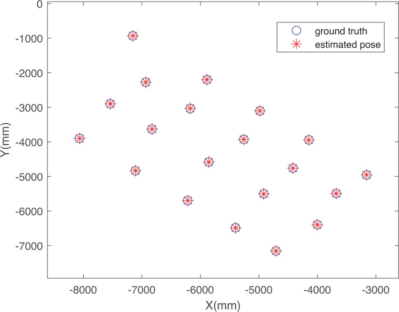
- FIGURE 14
This is the position of static vision localization. Red asterisks denote the vision results of the AGV pose. Blue circles denote the ground truth poses measured by the laser tracker.
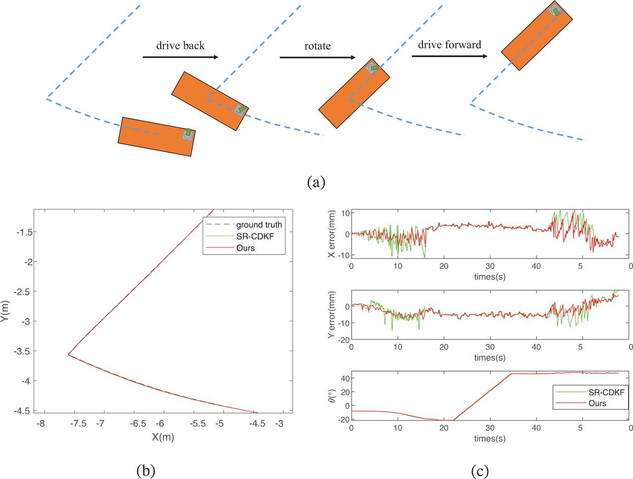
- FIGURE 15
(a) represents the path taken by the AGV in the localization experiment. The AGV starts with a backing process following a curve, and then rotates to change its direction. The remaining path is a simple forward line. (b) is a comparison of the real trajectory of AGV with the SR-CDKF estimated method and ours (VLPO + SR-CDKF). (c) depicts the attitude errors of the AGV, including the x-coordinate and y-coordinate. The ground truth of yaw angle θ cannot be measured in our experiment; thus, only θ is plotted. When AGV is driving back from 0~18 s, dcam becomes larger and the error becomes larger. When AGV is driving forward from 40~55 s, dcam becomes smaller and the error becomes smaller.


Tables
Number Position(mm) Angle(°) 1 4.136867620 -0.035228399 2 3.960575702 -0.048955928 3 3.876337586 -0.027618013 4 4.687936237 -0.009338273 5 3.801217524 0.026416594 6 4.366653928 0.013342928 7 3.633090001 0.035763361 8 1.891245422 0.003734939 9 5.450662837 -0.036851006 10 3.202877925 -0.051873036 11 4.801864309 -0.044247884 12 5.756986571 -0.019618353 13 1.190111912 0.012031608 14 4.202759910 0.031727095 15 4.126162090 0.013327649 16 0.797818209 -0.008425105 17 2.461203542 0.026433754 18 2.939329873 0.027528722 19 4.234428989 0.008643642 20 5.452405839 -0.021162262 Methods Position Accuracy Angle Accuracy Cost Adaptability for Spraying VLP (Zhuang et al., 2019) 11 cm Low General UWB (An et al., 2020) 20 cm 1.8° High High RFID (Tao et al., 2021) 30 mm General General IMU-UWB (He et al., 2020) 20 mm High High Laser SLAM (Cho et al., 2018) 10 mm 1° High General Visual Marker (Lee et al., 2013) 36 mm 2° General Low Vision with UWB (Hu et al., 2020) 15 mm High Low QR Code, Dual Camera (Tang et al., 2020) 10 mm 0.15° General Low LED lights on robot (Boutteau et al., 2020) 30 mm 1° General High Ours 10 mm 0.052° General High


Jump to section
Related Articles
Cited By...
- No citing articles found.