

Summary
The paper presents a modified Constant Envelope Multiplexing with Intermodulation Construction (CEMIC) technique for multiplexing signals within a single frequency band. A constant envelope signal is necessary to operate a transponder at maximum efficiency. This paper proposes a novel scheme to incorporate backwards compatibility constraints into the cost function of the existing CEMIC scheme to minimize changes in the onboard navigation system and ground receivers. The proposed scheme maximizes multiplexing efficiency by optimizing signal power sharing as per system requirements. Simulation results indicate that the proposed scheme provides 0.1% to 13.7% better efficiency than the existing CEMIC scheme, depending upon the case severity. Furthermore, the power distribution and phasing of the individual intermodulation constituent signals are optimized to minimize intra-system and inter-system interference. As a result, the proposed scheme facilitates frequency coordination with GNSS service providers. The paper also discusses the hardware performance of the proposed scheme’s composite signal.
1 INTRODUCTION
Satellite-based navigation provides multiple services like open service, restricted service, and commercial service over single carrier frequencies and multiple carrier frequencies. Multiple navigation services over a single carrier frequency require transmitting multiple signals from each navigation satellite. It requires onboard multiplexing of multiple navigation signals over the single carrier frequency before transmission from the satellite. Transmitting multiple satellite navigation signals over the same carrier frequency is required to utilize onboard hardware resources while supporting multiple navigation services effectively (Hegarty, 2012; Kaplan & Hegarty, 2017). The signal multiplexing schemes are designed to generate a constant envelope waveform to avoid non-linear distortion added by an onboard high power amplifier (HPA) operating under saturation conditions. Operating onboard HPAs under saturation conditions provides maximum power efficiency and better performance which is desirable for satellite design and operations.
The individual navigation signals to be transmitted are of binary phase shift keying (BPSK) or binary offset carrier (BOC) type (Betz, 2001) having constant modulus (CM). When only two CM signals are transmitted over a single carrier frequency, quadrature multiplexing both signals results in a composite signal with a constant modulus. When more than two CM signals are transmitted over a single carrier frequency, the resulting composite signal exhibits a non-constant modulus.
Numerous techniques are available in the literature for generating a constant modulus composite signal; nevertheless, converting a non-constant modulus signal to a constant modulus signal results in multiplexing loss (Yao & Lu, 2017). Multiplexing loss results from intermodulation components added with desired signals to make a constant modulus composite signal part of the multiplexing scheme. The intermodulation components in the composite signal, however, do not provide any information. Multiplexing loss reduces the effective transmission power of desired signals from satellites, affecting the overall link design or increasing the onboard HPA size requirement to compensate for multiplexing loss.
The GNSS community has carried out exhaustive research to minimize the multiplexing loss associated with the multiplexing scheme. The Interplex method provides the lowest multiplexing loss for transmitting three CM signals over a single frequency (Butman & Timor, 1972). However, the Interplex scheme for multiplexing more than three CM signals does not provide an optimum result in terms of multiplexing efficiency (Chen et al., 2021; Frye, 2017). Hence, it is intuitive to devise another multiplexing method to maximize multiplexing efficiency.
Another method to multiplex more than three signals is the Majority Vote (MV) method. The MV method is a non-linear method that statistically combines input signals depending upon the desired targeted ratio (Spilker Jr. & Orr, 1998). Although the MV method provides high multiplexing efficiency, its applicability is limited to the availability of its analytical expression required to estimate spectral characteristics of a composite signal. This detail is also necessary to estimate intra-system and inter-system interferences for coordination with other GNSS service providers (Querol et al., 2016). A hybrid of both the Interplex and MV method, known as the Intervote method (Cangiani et al., 2001), is also used for signal multiplexing. The advantage of the Intervote method is that it provides multiplexing efficiency better than the Interplex method (Cangiani et al., 2001).
Various iterative methods have been proposed in the literature to generate the constant envelope composite signal using amplitude and phase domain optimization approaches (Yao & Lu, 2017). A multiplexing scheme based on the phase domain processing of the input signal is carried out in the Phase Optimized Constant Envelope Transmission (POCET) method (Dafesh & Cahn, 2009). The POCET method provides better multiplexing efficiency for single frequency and bi-level input signals compared to Interplex, MV, and Intervote signal multiplexing methods (Dafesh & Cahn, 2009). Since, in the case of POCET, phases of the input signals are optimized to make the composite signal a CM, an approximate analytical expression is possible to derive (Yao et al., 2017).
In order to get an exact analytical expression of the composite signal, amplitude domain processing is preferable over phase domain processing. The Constant Envelope Multiplexing using Intermodulation Construction (CEMIC) scheme is known to be the most efficient scheme to multiplex multiple signals (more than three signals) over a single frequency by using amplitude domain processing (Zhang et al., 2012). It generates the constant envelope waveform with an arbitrary power ratio of signal components by adding intermodulation terms. The multiplexing efficiency of the CEMIC method is equivalent to the POCET method, and it is better than other multiplexing schemes like the Interplex, Intervote, and MV methods (Zhang et al., 2012).
GNSS service providers introduce many new navigation services like commercial services, modernized restricted services, and interoperable open services. They propose these new services in existing navigation satellites on the available carrier frequency, which is currently transmitting existing service signals, and/or on the new carrier frequency depending upon the available onboard resources and frequency coordination with other GNSS service providers. Thus, adding a new service signal in the existing service signal structure over a single carrier frequency would be challenging.
The inclusion of the additional signal should not affect the performance of existing signals. It is also important that adding the new signal to the existing signals over a single carrier frequency does not change the architecture of operational receivers. The adequacy of the transmitted power mainly governs the performance of navigation signals. The signal type and their relative transmission phase between other signals of the same and/or other services on the same frequency band govern receiver architecture. Hence, preserving the transmitted power and phase of the existing operational navigation signals for a given service is essential, commonly known as the Backwards Compatibility Condition (Bhadouria et al., 2021; Upadhyay & Bhadouria, 2021).
For practical purposes, it is necessary to develop a multiplexing scheme that takes into account the signal structure of existing operational navigation services. This paper presents a modified CEMIC-based multiplexing method to minimize the changes in the existing signals while achieving maximum multiplexing efficiency. The existing CEMIC scheme cost function is modified in the proposed method by incorporating the Backwards Compatibility Condition. We derived the modified cost function and new phase constraints from the existing signal structure information. Additionally, the proposed method is adaptable in terms of power distribution and phasing of the constituent signals.
This paper presents a comparative performance analysis of the modified CEMIC scheme compared to the existing CEMIC scheme. The simulation results show that the proposed modified CEMIC scheme performs better than the original CEMIC scheme in multiplexing efficiency and meets backwards compatibility conditions. In order to demonstrate the practical efficacy of the proposed method, the paper also presents a case study to multiplex an additional signal with the existing Indian Regional Navigation Satellite System (IRNSS) L5 and S-band signals using the modified CEMIC scheme. Furthermore, we provide the spectral characteristics of the constituent intermodulation terms for various modulation options of the additional signal to analyze intra-system interference and inter-system interference. This paper also presents actual hardware results to demonstrate the efficacy of the proposed multiplexing scheme.
The content of this paper is organized as follows: In Section 2, we present the problem formulation, which also includes the mathematical details of the general signal structure. Section 3 provides the details of the proposed modified CEMIC-based multiplexing scheme. The hardware and simulation results are given in Section 4. The conclusion of the work is given in Section 5.
2 PROBLEM STATEMENT
Navigation signals used by GNSS operators are typically generated by the Direct Sequence Spread Spectrum (DSSS) method. The transmitted bandpass DSSS navigation signal can be represented as:
 1
1
where ℛ{.} is the operator that outputs the real value of its argument, P is the power of the transmitted signal, fc is the transmitted carrier frequency, φ is the transmitted carrier phase, and sBB is the baseband equivalent of the transmitted signal given by:
 2
2
where bn represents the navigation data modulated by the ranging code, Fs = 1/Ts is the sub-carrier frequency, and κ (l) is the l-th element of shape vector κ. Ts is the sub-chip interval related to the chip interval as Ts = Tc/M. The modulation order M represents the number of half-cycles of the sub-carrier in the chip duration Tc. For BPSK, κ = 1 with M = 1 and for sine-phase BOC(1,1), κ = [1, −1] with M = 2. The pulse p(t) is given by:
 3
3
The combination of N independent DSSS signals at the single carrier frequency fc can be represented as:
 4
4
where (.)i represents i-th signal and the baseband equivalent sBB(i)(t) is represented as:
 5
5
where bn(i) represents the modulated navigation data of the i-th signal, Mi represents modulation order of the i-th signal, and Ts(i) represents the sub-chip interval of the i-th signal. pTs(i) is the unit amplitude rectangular pulse of the duration Ts(i) of the i-th signal. κ(i, l) is the l-th element of the shape vector of the i-th signal.
The effective baseband equivalent of the transmitted bandpass DSSS navigation signal is given by:
 6
6
As evident from Equation (6), depending upon the values of Pi, ϕi, and N, it was observed that the envelope of the composite signal is a non-constant modulus. Consider a case in which three signals s1, s2, and s3 are combined with a power of 0.2, 0.2, and 0.6 respectively. The initial phase values are 0, 0, and π / 2, respectively. If the signals are bi-level with the same chip rate Fc, the resulting constellation is shown in Figure 1. It was observed that the resulting signal was a non-constant modulus having two different modulus values (marked by the blue and the red arrows). In order to make the composite signal a constant modulus (CM), intermodulation terms were added and weights for each of the individual signals were optimized to get maximum multiplexing efficiency.

Constellation diagram of the linear combination of three signals
3 PROPOSED MODIFIED CEMIC METHOD
In order to multiplex multiple signals to generate a CM composite signal, the CEMIC method adds some intermodulation (IM) terms generated using a combination of desired signals in the composite signal. The resulting composite signal generated using the CEMIC method is represented as:
 7
7
where  and wj are the weight of the i-th desired signal and the j-th IM term, respectively, which are to be optimized. N and NI are the number of desired navigation signals and IM terms, respectively. From Equation (7), it is observed that the IM terms do not convey any useful information. Hence, the total power associated with the IM terms represents the multiplexing loss of the signal multiplexing method. Equation (7) is re-written as:
 8
8
where 
The multiplexing loss (L) is given by:
 9
9
where w = [w1, w2,…,wNI] and ||x|| are the norm of the vector x. Similarly, the efficiency of the multiplexing scheme is given by:
 10
10
In the conventional CEMIC-based method, the weight vector W is optimized to get a constant envelope signal while achieving maximum multiplexing efficiency. Hence, the cost function of the CEMIC method consists of the only multiplexing efficiency in its argument and constraints are defined in such a way that the resulting signal is a CM composite signal. However, as we already mentioned, besides maximizing the multiplexing efficiency, it is equally essential to preserve the existing signals’ performance while introducing additional signals on the same frequency band. It becomes imperative to include the information of the existing signal structure in the cost function of the optimization framework. Hence, we propose a modified CEMIC scheme with a new cost function to optimize weight vector W for generating a CM composite signal with maximum multiplexing efficiency and minimal impact on the existing service. The modified CEMIC scheme fuses the relative power-sharing and phasing values of the existing signal into the cost function (Bhadouria et al., 2021; Upadhyay & Bhadouria, 2021).
In the proposed method, the CM composite signal generation task is realized as the minimization of the following cost function:
 11
11
where b = [ejθ0, Z]T. Z is the zero vector with length NI and θ0 is the vector containing initialization phases of  weights. The Λ is the L × L diagonal matrix given by:
 12
12
where L is the length of the vector W which is defined by L = N + NI, I is the N × NI identity matrix, and ΛE is the N × N power-sharing preservation matrix denoted by:
 13
13
where εi is the penalty factor for i-th signal. Its value is decided on the basis of the allowable performance degradation in terms of reduction in allocated power of the i-th signal. Assuming 1-dB allowable degradation in targeted performance, ε ≈ 1.12. The receiver implementation for a particular GNSS service signal also depends upon the relative phasing of the signals multiplexed over the single frequency. Hence, it is important to keep the existing signal structure intact and multiplex the new signal while maintaining its phasing relationship. In order to minimize the implication of multiplexing an additional signal, we formulated the optimization problem as follows:
 14
14
such that:
 15
15
 16
16
where ∠(x) returns the phase vector consisting of the phases of the element of vector x, and  is the 1× N weight vector which is given by
  . The constraint given in Equation (16) is translated to the cost function using the method given in Yao et al. (2017). The representative cost function is given by:
 17
17
where G = diag(g1, g2,…,gNI) is the diagonal matrix whose entries are given by:
 18
18
where G+ represents the L / 2 higher values of the magnitude in sCE modulus, and G− represents the L / 2 lower values of the magnitude in sCE modulus. sCE is the equivalent representation of Equation (8) in terms of a DSSS modulated navigation signal given by:
 19
19
where C is obtained from the orthogonal basis expansion of C0 that contains the input DSSS modulated navigation signal as the column vectors given by C0 = [c1, c2,…,cN], where ci is the digital realization of sBB(i)(t). The constraint given in Equation (15) is included in the cost function given in Equation (11). However, it is a strict constraint that is to be followed by an optimized solution. Hence, only those solutions are considered, which follows Equation (15) in the strictest sense. In the proposed method, the optimization problem now becomes the minimization of the following cost function (𝒵(W)):
 20
20
where α1 and α2 are the weights of the respective cost function. The above optimization problem is solved using a gradient descent algorithm; the weight vector is updated based on the gradient of the cost function 𝒵(W) with respect to W. The gradient of the cost function 𝒵(W) with respect to W is given by:
 21
21
Using Equation (21), the gradient-descent-based update becomes:
 22
22
where µ is the step size control parameter and (.)i represents the i-th iteration step.
In this work, we propose adding a new cost function C(W) to the existing method cost function f(W). This affects the convergence rate of the optimization algorithm since the matrix Λ is a positive definite matrix that does not pose a limitation on the stability of the iterative solution. Furthermore, it is essential to note that optimization is a one-time exercise for designing the multiplexing scheme for onboard navigation payload systems. Hence, the algorithm’s convergence rate does not play a critical role as long as it maintains the stability of the algorithm.
The conventional CEMIC method maximizes the multiplexing efficiency based only on inter-modulation terms. On the other hand, the proposed modified CEMIC method provides flexibility to the existing cost function and results in better multiplexing efficiency than the conventional CEMIC method due to the following reasons:
It reduces the power allocated to IM terms to maximize multiplexing efficiency.
The proposed method also controls the deviation from the required power sharing of the desired signals. It, in turn, provides the advantage of maximizing multiplexing efficiency while meeting backwards compatibility requirements.
4 RESULTS AND DISCUSSION
4.1 Comparison of the Modified CEMIC Method with Original CEMIC Method
In this section, we evaluate and compare the performance of the proposed modified CEMIC method with the original CEMIC method. We simulated three cases based on variable power distribution. We organized simulated cases based on the increasing complexity of the constellation points’ power variability of the original linearly combined signal, i.e., without constant envelope multiplexing (CEM). We evaluated both methods for multiplexing four signals with given targeted power and phasing distribution. This experiment examined the impact of multiplexing on its efficiency, deviation from the existing signals’ power sharing and relative phasing, and constant envelope signal generation. In this simulation, we used cost function weighting parameters α1 = 10 and α2 = 1. The cost function C(W) typically has a lesser magnitude than the cost function f(W). Thus, we considered a higher value of α1 to compensate for this effect. We considered the step size parameter of µ = 10–4 for all cases in this simulation.
4.1.1 Case 1: Power Variation Only Along the Quadrature Axis
The targeted power sharing (i.e., P0) and relative phasing (i.e., ϕ0) of the four signals to be multiplexed for Case 1 is given by:
 23
23
 24
24
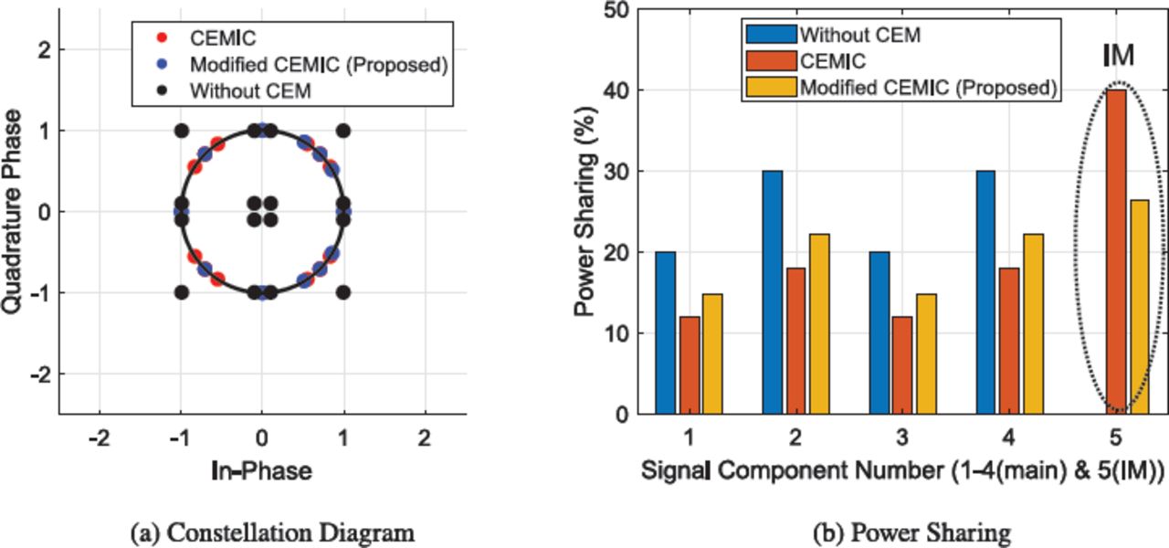
Figure 2(a) shows the constellations of the given power and phasing distribution. It is the best case in terms of multiplexing efficiency since it has power variation only along the in-phase dimension with a more considerable distance between the constellation points and the origin. Furthermore, it can also be observed that shifting the constellation points on the unit magnitude circle (constant modulus) requires less intermodulation power. This is due to the distribution of the constellation points nearer to the unit circle. Hence, the multiplexing efficiency is higher in this case.

Comparison of the modified CEMIC method with the original CEMIC method for Case 1
Figure 2 shows optimized results for both methods. We observed that both methods converged at the same constellation points. It also shows that both methods had equivalent performance for Case 1, as shown in Figure 2(b). We also observed that both methods had approximately the same reduction in the desired signal component’s power (marked by signal components 1 through 4). Moreover, the same power transferred to the intermodulation (IM) terms (marked by the signal component 5). This indicates that both methods were equivalent in terms of multiplexing efficiency for Case 1. Details of the power sharing of the individual signals are given in Table 1. The proposed method has an advantage of around 0.1% in terms of multiplexing efficiency.
Power Sharing Comparison
4.1.2 Case 2: Power Variation Along Both Axes
In this case, we kept two signals in the quadrature phase. The targeted power sharing (i.e., P0) and relative phasing (i.e., ϕ0) of the four signals to be multiplexed for Case 2 is given by:
 25
25
 26
26
As a result, it is evident from Figure 3(a) that it has power variation along both the dimensions (i.e., in-phase and quadrature). Moreover, Case 2 also had a more significant power variation among the constellation points compared to Case 1. It demanded more IM signal power to generate a constant envelope signal. The constant envelope multiplexing schemes were, in general, less efficient for Case 2 as compared to Case 1.

Comparison of the modified CEMIC method with the original CEMIC method for Case 2
We observed that the optimized constellation points for both methods were different. Figure 3(b) shows the advantage of the proposed modified CEMIC method over the original CEMIC method in terms of both the deviation from the desired power sharing and multiplexing efficiency. Table 1 quantifies the performance of both the methods in which the proposed modified CEMIC method had a smaller deviation from the desired power sharing compared to the original CEMIC method. At the same time, the proposed modified CEMIC method performed better in terms of multiplexing efficiency.
4.1.3 Case 3: Power Variation Along Both the Axes with Constellation Points Near Origin
Case 3 was more complex in terms of multiplexing compared to both Case 1 and Case 2. The targeted power sharing (i.e., P0) and relative phasing (i.e., ϕ0) of the four signals to be multiplexed for Case 3 is given by:
 27
27
 28
28
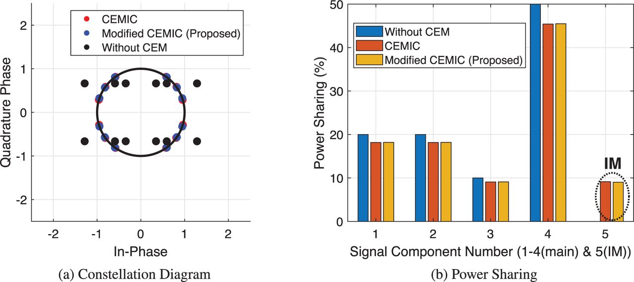
In this case, we kept two signals in the quadrature and two signals in-phase. We considered a uniform power-sharing distribution (i.e., all the constituent signals would share approximately equal power). As a result, the constellation points became closer to that of origin. Accordingly, intermodulation terms required higher power to make the composite signal a constant modulus, making the multiplexing schemes less efficient. Figure 4 shows the performance of both methods (i.e., the original CEMIC method and proposed modified CEMIC method). Figure 4(a) shows the optimized constellation diagrams of both methods. Results show that both methods converged at different constellation points resulting in a different optimum solution.
Comparison of the modified CEMIC method with the original CEMIC method for Case 3
Furthermore, the constellation of the original CEMIC method remains symmetric while the proposed modified CEMIC method resulted in an asymmetric constellation. The prime reason for this behavior is that the proposed modified CEMIC method has a non-zero value of the coefficients of the even cross product of the constituent signals as given in Table 1. In the proposed method, fusing the backwards compatibility constraints into the cost function provides the flexibility of getting an asymmetric constellation. It is to be noted that the asymmetric constellation in composite navigation signal does not pose any disadvantage. However, the result had significantly better multiplexing efficiency compared to the original CEMIC method.
It is evident from this discussion that the proposed modified CEMIC method is more robust in terms of both minimization of the deviation from the desired power sharing and required multiplexing efficiency. Moreover, the performance of the proposed modified CEMIC method provides significantly better results for the cases that require higher intermodulation power for constant envelope signal multiplexing.
4.2 Case Study: Modified CEMIC Scheme for IRNSS Signal Structure
As a case study, the proposed method was evaluated for the Indian Regional Navigation Satellite System (IRNSS).
IRNSS currently provides a standard positioning service (SPS) and restricted service (RS; Mruthyunjaya & Ramasubramanian, 2017). As a case study, the modified CEMIC scheme was optimized for IRNSS L5 and S-band signals to add future service signals and present SPS and RS signals. It was used to multiplex four desired signals: present SPS data signals, RS data and pilot signals, and an additional signal. IRNSS L5 and S-band payloads used an Interplex modulation scheme to multiplex three signals (i.e., SPS data signals, RS data signals, and RS pilot signals) to generate constant envelope modulation signals. Multiplexing an additional signal over the existing L5 and S-band signals reduces the efficiency of the transponder with the existing Interplex multiplexing scheme. The proposed modified CEMIC scheme was optimized to generate a constant envelope waveform to minimize the impact of adding signals to present IRNSS L5 and S-band signals. The proposed modified CEMIC scheme was optimized for IRNSS L5 and S-band signals with the following constraints:
Better multiplexing efficiency ρ0 ≥ 089.
Maintaining the phasing of present SPS and RS signals (i.e., phase constraint)
Minimum change in the power sharing of present SPS and RS signals (i.e., power-sharing constraint)
Minimum changes in present system configuration
Controlling intermodulation products with desired phasing to minimize intra-system interference
Two different multiplexing options (i.e., Option 1 and Option 2) were optimized with a modified CEMIC scheme and compared with the present IRNSS L5 and S-band signals’ power composition shown in Table 2. It compares the power sharing of both options using the proposed method to the power sharing of existing signals of the IRNSS. In Option 1, the maximum allowable degradation of the RS pilot signal was kept below 0.6 dB, and in Option 2, it was kept below 1.4 dB. It is evident from Table 2 that the maximum power reduction was limited to –0.55 dB for Option 1 and –1.35 dB for Option 2. In this paper, for analysis purposes, the modulation characteristic of the additional signal was considered to be BOC(5, 2), BOC(10, 1), and BPSK(2) for the proposed scheme. However, the proposed modified CEMIC scheme did not limit choosing any binary waveform spectral characteristics for the additional signal. The minimum separation angle in the constellation points was 18.9° and 37° for Option 1 and Option 2, respectively.
Power Ratio for the Two Proposed Modified CEMIC Options
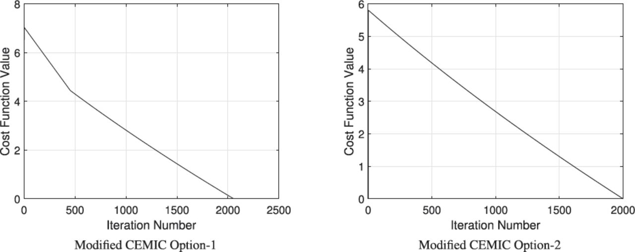
Constellation diagrams of both proposed modified CEMIC options are shown in Figure 5. The convergence behavior of the gradient-descent-based algorithm is shown in Figure 6. It indicates that the options’ convergence rate was different even for the exact value of the step size parameter µ. The convergence rate depends upon the variance of magnitude values of the initial linear combination configuration. Although in Figure 5, it appears that the proposed method had a strictly constant magnitude, in the actual case, there was finite residual variation in the magnitude of the final converged solution.

Constellation diagram of the proposed options

Optimization performance using gradient-descent-based algorithm
This residual variation stemmed from the weight vectors’ quantification and the step size parameter µ, which was controlled by optimizing the step size. For both proposed options, amplitude variation was of the order of 10–4 for the step size value of 10–5. It is to be noted that the proposed scheme generated a constant envelope waveform considering the additional signal with any binary waveform spectral characteristics. Power spectral density (PSD) of the proposed modified CEMIC options assuming the additional signal modulation characteristic to be BOC(5, 2), BOC(10, 1), and BPSK(2) are shown in Figure 7.

Power spectral density (PSD) of the proposed options
This paper also evaluated the impact of individual intermodulation products on overall system performance for the proposed modified CEMIC options considering all candidate modulation schemes for the additional signal transmission. Table 3 shows the spectral characteristics of individual intermodulation constituent signals and their power sharing. It is observed that, in selecting the additional signal to be BPSK(2), the intermodulation power was more concentrated over BOC(5, 2) compared to the other two options of BOC(5, 2) and BOC(10, 1). This effect was present for both of the proposed modified CEMIC options.
Effective Spectrum of Intermodulation Components
An increase in the power of the BOC(5, 2) component due to intermodulation signals increased self-interference to present RS BOC(5, 2) data and pilot signals. Further, it was observed from the results that selecting the additional signal to be BOC(10,1) improved the self-interference scenario to present IRNSS SPS and RS signals. Thus, it became necessary to optimize the power sharing and the phasing of individual intermodulation constituent signals generated due to multiplexing multiple signals and analyzing their impact on performance.
In order to validate the performance of the proposed scheme in the actual scenario, we generated a composite signal on hardware and monitored the performance. The impact of the navigation payload onboard output filter on the performance of the composite signal was analyzed using the hardware-generated signal. The navigation payload onboard output filter was a significant source of signal distortion added by navigation payload onboard subsystems, which degraded the transmitted composite signal constellation quality by causing inter-symbol interference (ISI). The overall impact of the onboard filter on the composite signal constellation was quantified in terms of the incurred error vector magnitude (EVM), which is a performance metric for the evaluation of navigation payloads (Upadhyay et al., 2014; Wara et al., 2018).
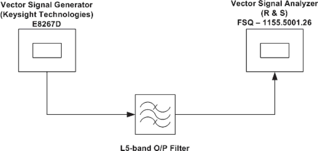
An experimental setup is shown in Figure 8. The IRNSS payload qualification model L5-band output filter was used in the experiment. The parameters used for the experiment are given in Table 4.

Experimental setup
Parameters for Experimental Setup
Measured power spectral density (PSD) and modulation performance of hardware-generated signals are shown in Figure 10. In this experiment, the additional signal was considered to be BOC(5,2) modulation, evident from the given PSD in Figure 10. The measured EVM of the composite signal was around 5% and 7% due to the combined effect of onboard output filter and modulator (vector signal generator) impairments for Option 1 and Option 2, respectively. It shows that the received symbols successfully demodulated without interfering with each other.
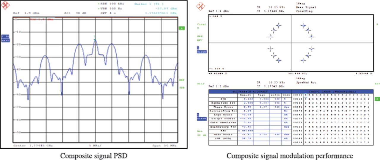
Modified CEMIC Option 1 hardware results at the L5 band with output filter

Modified CEMIC Option 2 hardware results at the L5 band with output filter
5 CONCLUSION
We propose a modified CEMIC scheme for multiplexing multiple signals over a single frequency band to incorporate an additional signal into the existing navigation system. The proposed scheme maximizes multiplexing efficiency by optimizing the power sharing of desired signals based on system requirements. The proposed scheme maintains the phasing of individual signals already present in the system to ensure compatibility with all operational receivers. Moreover, the proposed scheme performs better than the conventional CEMIC scheme in terms of multiplexing efficiency. It reduces the onboard multiplexing loss and diverts more power to the desired signals.
We also analyzed the power sharing and phase of individual intermodulation constituent signals generated due to multiplexing processes minimizing intra-system interference and inter-system interference. Such analysis provides better frequency coordination flexibility with other GNSS service providers. As an illustrative example, the proposed scheme was optimized for various power-sharing and phasing configurations in order to generate a composite constant envelope waveform for IRNSS L5- and S-band signals in order to add signals to the current configuration. The paper also discusses the performance of the composite signal generated on actual payload hardware using the proposed scheme. The proposed scheme can be modified to multiplex multiple frequency signals to generate a constant modulus composite signal.
HOW TO CITE THIS ARTICLE
Bhadouria, V., Upadhyay, D., Majithiya, P., & Bera, S. (2022) Modified CEMIC scheme for multiplexing signals over single frequency band. NAVIGATION, 69(3). https://doi.org/10.33012/navi.528
ACKNOWLEDGEMENTS
The authors are grateful to Shri. K. S. Parikh, Deputy Director, Satcom & Navigation Payload Area and Shri. Sumitesh Sarkar, Group Director, Satcom & Navigation Systems Integration and Checkout Group of Space Applications Center, Indian Space Research Organisation for their support, guidance, and encouragement during the work.
Footnotes
0 Abbreviations: BPSK, binary phase shift keying; BOC, binary offset carrier; GNSS, global navigation satellite system
This is an open access article under the terms of the Creative Commons Attribution License, which permits use, distribution and reproduction in any medium, provided the original work is properly cited.


Jump to section
Related Articles
Cited By...
- No citing articles found.