Abstract
In this article, we present the design of a new navigation message system that includes an error-correcting scheme. This design exploits the “carousel” nature of the broadcast navigation message and facilitates (i) a reduction in the time to first fix (TTFF) and (ii) enhanced error-correcting performance under both favorable and challenging channel conditions. We show here that this combination design requires error-correcting schemes characterized by maximum distance separable (MDS) and full diversity properties. Error-correcting Root low density parity check (Root-LDPC) codes operate efficiently to block various channels and thus can permit efficient and rapid recovery of information over potentially non-ergodic channels. Finally, to ensure appropriate data demodulation in harsh environmental conditions, we propose the use of Root-LDPC codes endowed with a nested property which will permit them to adjust the channel coding rate depending on the number of information blocks received. The proposed error-correcting combination design was then simulated and compared with the well-known GPS L1C subframe 2 using several different transmission scenarios. The results of these simulations revealed some enhancement of the error-correcting performance and reductions in TTFF in several specific situations.
1 INTRODUCTION
Precise positioning, navigation, and timing information are all required features in new applications, for example, intelligent transportation systems (ITS), automated aircraft landing, and autonomous unmanned ground/air vehicles. For these types of applications, the global naviation satellite system (GNSS) is the main source of positioning information (Teunissen & Montenbruck, 2017). This technology has attracted significant interest in recent years not only because of its reliability and integrity but also as a means of authenticating a legitimate transmission.
In recent years, the principal working groups in charge of the design of the new generation of GNSS signals have chosen to include error correcting codes, including low-density parity-check [LDPC] or convolutional codes (Galileo-ICD, 2021; GPSL1C-ICD, 2021) that enhance data demodulation performance. Moreover, the results of several recent studies (Ortega et al., 2018a, 2018b, 2018c, 2020; Schotsch et al., 2017) focused on reducing the time to first fix (TTFF) in the GNSS system have motivated the design of novel channel coding schemes that aim to decrease the time to retrieve the clock and ephemeris data (CED), also called time to data (TTD). These schemes exploit maximum distance separable (MDS) methods (Boutros et al., 2010) to decode reliable data as rapidly as possible. In several other publications (Ortega et al., 2018a; Schotsch et al., 2017), channel coding schemes that exploit both serial concatenation and MDS methods were proposed to reduce the TTD and also to improve the demodulation threshold of the CED. As a group, these schemes combine error-correcting and error-detecting techniques to ensure the robustness of the CED. However, as shown by Ortega et al. (2020) these channel coding schemes do not generate error corrections during GNSS outages (Boutros et al., 2010). Hence, data resilience can be degraded in harsh environments.
To enhance error correction performance, we propose a new method that will address both the navigation message structure and the channel coding scheme (Ortega et al., 2018b 2020). This method models navigation message acquisition as block fading channels with erasures (Biglieri et al., 1998). Thus, the navigation data and the redundant bits from the channel encoder are divided into different information blocks that are capable of reflecting different channel conditions (i.e., each information block is affected by a different fading coefficient). In the case of deep fading, the information block can be assumed missing (i.e., the information block is erased). In this context, the received navigation message can be modeled as follows: (i) some information blocks will be received with errors and different average signal-to-noise (SNR) ratios and (ii) some information blocks will be missing. Based on this novel design, we derived a method to retrieve the CED when blocks of information were missing. This resulted in a channel coding scheme that maintained the MDS property. Moreover, by using the navigation message acquisition model, a second desired property, i.e., full diversity, was also introduced. This property allows us to exploit the entire diversity of the channel to improve data demodulation in harsh environments. In Ortega et al. (2018b), we proposed a combination design that included the message structure and the channel coding based on a regular Root-LDPC (Boutros et al., 2010) codes of rate R = 1/2. These error-correcting methods will achieve both MDS and full diversity when applying the Min-sum or the belief-propagation (BP) decoding algorithms as long as the CED and the redundant data generated by the channel encoder are divided into two blocks. An extension of this work was proposed by Ortega et al. (2020). In this extension, an irregular protograph Root low density parity check (Root-LDPC) code of rate R = 1/2 was designed to improve the error-correcting capabilities (i.e., the convergence and demodulation threshold) under the BP algorithm. Furthermore, two independent block-interleaves were proposed in order to average the channel over each of the information blocks.
The previous error-correcting schemes facilitated reductions in the TTD and enhanced the error-correcting performance for low carrier-to-noise ratio (C / N0) environments. However, these channel coding schemes may be limited in terms of error-correcting performance in harsh environments, including scenarios with substantial fading and jamming. Furthermore, considering that the new generation of commercial receivers are expected to acquire and track signals under extremely low C / N0 environments, new combination designs with enhanced error-correcting capabilities are needed.
In this paper, we exploit the “carousel” nature of the broadcast navigation message to design a channel coding scheme that can fulfill these requirements. This design, which links the navigation message and the error-correction scheme, is based on a family of nested Root-LDPC codes (Ortega & Poulliat, 2021). This will permit the channel coding rate to adapt depending on the number of received blocks. The demodulation threshold will then be improved by combining different received blocks which will permit a lower channel coding rate at the decoder.
1.1 Contributions
In this paper, we present a methodology that can be used to build channel coding schemes designed with the navigation message which are characterized by properties that include the MDS and full diversity as well as the capacity to combine different information blocks to mimic a lower channel coding rate at the decoder. In order to design the error-correcting structures, we start by modeling the message structure acquisition by considering a block fading channel with erasure. Thus, the data and the redundant information from the encoder are divided into different information blocks. Two different schemes are proposed and analyzed:
The first scheme proposes the use of a simple regular nested Root-LDPC code of rate R = 1/3 and splitting the information and redundant data into three different blocks. This extends our earlier work by splitting the navigation message over more information blocks. This simple scheme aims to show that this message structure can enhance the performance over the existing proposition. To this end, we verify that the error correction performance depends on the number of received blocks and that it is independent of the received blocks. Moreover, in order to improve the error correction performance in fading environments, we include independent block-interleavers (i.e. one per information block) to take into account channel variations that are smaller than one received block. Note that this interleaving strategy is used to average the channel over each received block.
We then extended the previous scheme to the irregular case by considering protograph-based nested Root-LDPC structures of rate R = 1/3. The proposed family imposes a protograph structure that can be optimized to enhance the error correction performance using the BP decoding algorithm. Following Ortega & Poulliat (2021), we designed protographs based on the PEXIT-Chart method described by Liva & Chiani (2007). This will permit us to optimize the demodulation threshold of the error-correcting scheme. As in the preceding case, we include several block-interleavers to facilitate averaging the channel over each received block.
The two error-correcting schemes with a new message structure were simulated and compared to one another. The proposed schemes were also compared to the GPS L1C CED error-correcting scheme (GPS-L1C-ICD, 2021) that was considered a benchmark system. Part of this work was already published by the authors Ortega et al. (2019).
The paper is organized as follows: Section 2 reviews the requirements for the message structure and the desired channel coding properties which were designed to reduce the time to retrieve the CED. Section 3 presents the error-correcting solutions. The performance of these solutions is presented and analyzed over the block fading channel in Section 3.4. TWe then present the performance over standard channels such as additive white Gaussian noise (AWGN), jamming, and urban channels in Section 3.5. Our conclusions are presented in Section 4.
2 CO-DESIGN OF MESSAGE AND STRUCTURE WITH DESIRED CHANNEL CODING PROPERTIES
Over the past few years, the GNSS community has addressed the need to design rapid and robust GNSS acquisition signals. While several aspects must be taken into account when designing a new rapid acquisition component, the most important criterion is to provide the lowest possible TTFF. The TTFF is defined as the time needed by the receiver to calculate the first position fix. This time can be defined as the contribution of different times and depends not only of the navigation message design but also the quality of the receiver hardware. Among the different components, the major time contribution is that needed to retrieve the CED (Schotsch et al., 2017), denoted as the TTD. The navigation message acquisition model which facilitates a reduction in the TTD was first proposed by Ortega et al. (2018b, 2020). This model focuses on reduction of the TTD under high C / N0 environments while preserving its performance under low C / N0 channel conditions. This model was based on a GNSS receiver with no stored data (i.e., cold start scenario). Under this scenario, the GNSS receiver can begin to acquire the information broadcast by any GNSS satellite at any symbol period within the navigation message. Optimal TTD has been achieved if the first acquired symbol corresponds to the first information symbol of the CED; otherwise all the navigation messages must be received to be able to decode the CED.
Based on the preceding concept (Ortega et al., 2018b, 2020), a data navigation acquisition model was proposed as a block fading channel with block erasures. Figure 1 illustrates a codeword under the block fading channel scenario. We define t = 1, ⋯, nc as the index of the fading blocks. This model allows us to consider the missing navigation data as erased information blocks and the received navigation data as recovered information with different average SNR ratios. Based on this model, we identified a way to design the navigation message and the channel coding that allows us to decode the CED even if some parts of the navigation message were missing. As the receiver does not need to collect all the navigation data to decode the CED, the TTD can be reduced. As shown by Ortega et al. (2018b, 2020), the combination design also provides a navigation message structure that reduces the TTD. The proposed structure and the various assumptions and constraints can be summarized as follows:
CED and redundant data (from the channel encoder) are divided into several blocks. At the receiver, any block that has not been received will be considered by the decoder as erased.
A cyclic redundancy check (CRC) code must be included within the CED. This CRC code is used to check the integrity of the CED.
The design must provide a method to decode the CED even if some information blocks are missing/erased. However, the error-correcting capabilties are limited by the amount of missing information. Therefore, if the CRC detects an error, the receiver can wait for missing/erased blocks to arrive to enhance the error-correcting performance. This flexibility at the receiver is required to retrieve the CED in harsh environmental conditions.
Assuming that the CED and redundant data are part of a codeword, a design scheme cannot allow the use of complete codeword interleavers. Indeed, this structure requires the receipt of the entire codeword in order to decode the CED. Consequently, a design scheme with an interleaver that spans the entire code word cannot will not reduce the TTD beyond that achieved by existing systems.
Block fading message structure
2.1 Desired Code Properties
To design channel coding schemes suitable for the block fading channel with erasures, three main properties are required:
MDS;
full diversity; and
the ability to mimic the channel coding rate (Ortega & Poulliat, 2021).
Let us consider an error correcting scheme that provides code words divided in n blocks of equal size. We further assume that the CED is embedded into k blocks of which k < n are of the same size. The MDS property allows the system to retrieve k data blocks with systematic information from any k error-free blocks received. Based on this property, we can reduce the TTD under high C / N0 environments; with only k error-free blocks, the CED can be easily retrieved. However, there are several references in the literature (Boutros et al., 2010; Guillen i Fabregas & Caire, 2006; Knopp & Humblet, 2000) in which error-correcting schemes with MDS exhibit poor error-correction over a block fading channel because they were unable to achieve the full diversity of the channel.
Definition 1. An error correcting code C is said to have full diversity over block fading channel if the diversity order is equal to the number of fading blocks nc. The diversity order determines the slope of the error-rate curves as a function of the signal-to-noise ratio (SNR) on a log-log scale for the Rayleigh fading distribution as shown in Equation (1):
 1
1
where Pew is the codeword error probability at the decoder output and γ is the average SNR. The Pew of a code with full diversity nc decreases as 1/ γnc at high SNR. Since the error probability of any coding/decoding scheme is bounded at the lower end by the outage probability Pout, the diversity order is upper-bounded by the intrinsic diversity of the channel which reflects the slope of the outage limit. When maximum diversity is achieved by a code, the coding gain yields a measure of “SNR proximity” to the outage limit. This optimal design yields the optimal code, which is given by the Singleton bound as shown in Equation (2):
 2
2
Codes achieving the Singleton bound are termed MDS. MDS codes are outage-achieving over the (noiseless) block-erasure channel, but may not achieve the outage probability limit on noisy block-fading channels and thus a good coding gain. MDS codes are necessary but not sufficient to approach the outage probability of the channel. Rather, full diversity is the desired and sufficient condition needed to approach the outage probability. Note that, as shown in Equation (2), in order to reach a full diversity code (d = nc), the maximum achievable rate is R = 1/nc. MDS and full diversity properties are achieved by the family of Root-LDPC codes (Boutros et al., 2010) under an iterative BP decoding algorithm. This family of structured codes is characterized by a new check node structure, referred to as rootcheck node. This check node structure permits more than one erasure bit to be tolerated under a BP decoding algorithm. For example, considering a block fading channel with nc = 2, a rootcheck Φ(x1, x2, …, xy) for a binary element x1 transmitted on fading α1 is a checknode where all bits x2, …, xy are transmitted on fading α2.
Finally, we search for error-correcting structures of rate 1/n which are inherently able to adjust the channel coding rate as a function of the number of received data blocks. Thus, we searched for a code structure in which the codeword was divided into n blocks and the information bits could be decoded over the block fading channel (with nc = n) with a diversity order equal to r given r < n as the number of received data blocks. In this case, the information achieves full diversity when r = nc. Moreover, the error-correcting structure should provide equal coding gain, independently of the received blocks. Likewise, the error correction performance only depends on the number of received blocks. As one example, let us consider a family of structured codes with rate 1/3 over a block fading channel with nc = 3. When only r = 2 blocks are received, the information bits should be decoded with a diversity order equal to those decoded by a Root-LDPC code structure with a rate 1/2 over a block fading channel with nc = 2.
3 PROPOSED ERROR-CORRECTING SCHEMES OF RATE 1/3
In this section, we present a regular LDPC code structure with MDS and full diversity as well as the capacity to combine various information blocks to adjust the channel coding rate (also called its nested property). Based on these combined properties, the decoder can reduce the TTD and provide enhanced error-correcting performance and a lower demodulation threshold (Ortega et al., 2018c). We then extend this coding structure to the irregular case and show that it improves the previous channel coding structure by optimizing via a protograph-based design approach. Thus, the following schemes will be analyzed:
Regular Nested Root-LDPC code of rate 1/3,
Irregular Nested Protograph Root-LDPC code of rate 1/3.
To simplify this presentation and provide an illustration of the proposed message broadcasting strategy, we consider only the design of error-correcting schemes of rate R = 1/3. However, as shown previously (Ortega & Poulliat, 2021; Ortega et al., 2019), lower coding rates can also be considered by extending the design method shown here.
3.1 Nested Root-LDPC Codes of Rate 1/3
In this section, we present a family of nested Root-LDPC codes of rate 1/3 (Ortega et al., 2019). For this family of codes, it is assumed that the overall message (i.e., the CED and redundant data from the channel encoder) is split over three information blocks and includes the following characteristics:
The MDS property, which allows it to retrieve the CED from any information block that is free of errors.
Full diversity over the block fading channel when the BP algorithm is used. This facilitates decoding of the CED with a diversity order equal to the number of information blocks received.
Moreover, when the receiver has already received r = 2 information blocks, the CED can be decoded with a diversity on the order of 2. Moreover, the same coding gain is achieved independently of the received information block. This property is referred to as the nested property.
Each systematic codeword (corresponding to the CED information together with redudant data) is divided into 3 information blocks, each containing some information and some redundant data. More precisely, considering a codeword of length N = 1800 bits, each information block includes N / 9 = 200 bits of information and 2 N / 9 = 400 bits of redundant data. Note that since the coding rate is R = 1/3, each information block will be composed of N / 3 = 600 bits. The LDPC code base matrix can be described by Equation (3) as follows:
 3
3
where Ii,j and 0 are N / 9 × N / 9 identity and all-zero matrices respectively. hi,j are submatrices with same Hamming weights per row and column. Moreover, the sub-indexes i and j represent the row and the column position within the base matrix. Moreover, the base matrix requires the following Hamming weights symmetry |h3,1| = |h6,4| = |h2,7|, |h5,1| = |h1,4| = |h4,7|, |h3,2| = |h6,5| = |h2,8|, |h5,2| = |h1,5| = |h4,8|, |h3,3| = |h6,6| = |h2,9|, |h5,3| = |h1,6| = |h4,9|. Note that |·| represents the Hamming weight. The Hamming weight distribution used for this error-correcting structure is the regular structure (4,6), i.e., |hi,j| = 1 when j = {1, 4, 7}, otherwise |hi,j| = 2.
3.2 Navigation Message Structure Adapted to Nested Root-LDPC of Rate 1/3
Based on the structure presented in Ortega et al. (2018b, 2020), the structure is composed of a series of messages with the same structure as the GPS L1C message (GPS-L1C-ICD, 2021). The reader may refer to Figure 2 to review the GPS L1C signal structure and Figure 3 for an example of the proposed message structure). Each message is split into three different parts. The first part contains 52 bits used to demodulate the Time of Interval (TOI) (GPS-L1C-ICD, 2021). The second part contains the CED and redundant data required to apply an error-correcting algorithm at the receiver to demodulate the CED. Finally, the third part (also known as the subframe 3) contains 274 bits of additional information and 274 bits of redundant data (called “Data 1” in Figure 2 and “Redundant Data 1”). This calculates to 1800 bits per message. Since the GPS L1C signal is transmitted with a rate of 100 bits/second, the demodulation time of the GPS L1C message is 18 seconds. The difference between the GPS L1C and the proposed message structure is that while the second set of GPS L1C information (i.e., CED and redundant data) is the same for each message, there are three possible types of messages in the newly-proposed navigation message. The detailed structure is as follows:
The first message sends the first and the second information blocks which contain 2/3 of the CED (400 bits) and 2/3 of the redundant data (800 bits). We can use these data to retrieve the CED with the same resilience as a Root-LDPC code of rate 1/2.
The second message sends the third and the first information blocks which contain 2/3 of the CED (400 bits) and 2/3 of the redundant data (800 bits). As above, we can use these data to retrieve the CED with the same resilience as a Root-LDPC code of rate 1/2. Moreover, if we have already received the first message, we can enhance the resilience of the data since we have already received the preceding 200 bits of CED and the 400 bits of redundant data, which is equivalent to a channel coding scheme of 1/3.
The third message sends the second and the third information blocks which contain 2/3 of the CED (400 bits) and 2/3 of the redundant data (800 bits). As above, we can use these data to retrieve the CED with the same resilience as a Root-LDPC code of rate 1/2. Moreover, if we have already received the second message, this will enhance the resilience of the data.
GPS L1C navigation message structure
Navigation message structure for a nested Root-LDPC of rate 1/3
In principle, one might think that sending more information will result in more time needed to demodulate the CED. However, since the proposed codes are MDS, under good channel conditions, it is possible to retrieve the CED when only one information block has been received. Thus, the proposed structure can reduce the TTD. Futhermore, in the GPS L1C structure, only one interleaver is used within the second and third part of the message to improve the channel diversity. The use of this type of interleaver enforces the notion that the TTD cannot be reduced. To improve the channel diversity over the block fading channel with nc > n in this proposed navigation structure, we might include a block-interleaver for each of the information block (as has been proposed for the Root-LDPC codes described by Ortega et al. (2018c)). Note that including a block-interleaver will enhance the channel diversity at the receiver without increasing the TTD of the nested Root-LDPC message structure.
3.3 Construction of Protograph-Based Irregular Nested Root-LDPC Codes of Rate 1/3
The preceding regular case can be used to analyze the desired properties of the proposed navigation message structure. However, as the variable node degree does not lead to practical schemes, encoding and mapping the information bits within the ik classes becomes an issue. For real-life implementation, small modifications of the structure are applied to obtain structures amenable to encoding. However, the properties of these codes may slightly differ from those obtained theoretically for regular codes.
In this section, we will explore protograph nested Root-LDPC codes which facilitates the desing of codes that lead to practical solutions with optimized demodulation thresholds when two or three blocks information blocks have been received. Considering the base matrix in Equation (3), we adopt the following general protograph representation (Thorpe, 2003) as shown in Equation (4):
 4
4
where  and j ∈ {1, ⋯, n}, represent possible parallel edges in the protograph representation (Thorpe, 2003). Note that if we use the protograph EXIT (PEXIT) chart algorithm proposed by Liva & Chiani (2007) to search for coefficients *, the retrieved matrix is not necessarily symmetrical between the different blocks. As a consequence, the base matrix does not ensure the required Hamming weight symmetrical pattern needed to fulfill the nested property.
Considering this fact and setting unknown ‘ *’ to be coefficient weights ∈ (0,1,2,3), we applied the optimization procedure proposed by Ortega & Poulliat (2021):
We searched for the subset of protograph matrices that provided the symmetrical pattern of the base matrix in Equation (3).
We computed the demodulation threshold over the ergodic channel (i.e., the AWGN channel) when only two blocks were received. This was achieved by computing the PEXIT chart algorithm with one erased block, i.e., considering that the channel mutual information provided by the erased block was Iαt = 0. Verification can be achieved quite simply (Ortega & Poulliat, 2021); if the protograph base matrix ensures a symmetrical pattern, the observed demodulation threshold is independent of the received blocks.
We computed the demodulation threshold over the ergodic channel when the entire codeword was received (i.e., when the three blocks were received). In this case, we compute the PEXIT chart algorithm by considering the ergodic AWGN channel.
We then proceeded to select the protograph structure that minimized the demodulation thresholds from the previous steps. Note that some protograph structures can provide low demodulation thresholds for the second step but high demodulation thresholds for the third step. Here, we looked for the protograph structure that minimized the demodulation threshold of the second step, considering that the demodulation threshold in the third step was lower that the structure provided in Section 3.1.
By applying this procedure, we generate the following base matrix:
 5
5
As previously mentioned, we proposed to add a block-interleaver associated with each information block to enhance the diversity of the channel. Regarding the encoding, most of the existing strategies for generating LDPC codes can be applied. In particular, because we are dealing primarily with protograph LDPC codes to produce quasi-cyclic structures, existing efficient encoding methods are available as described by Li et al. (2006).
3.4 Evaluating the Nested Root-LDPC Family Properties Over the Block Rayleigh Fading Channel
In this section, we present our analysis the performance of the two proposed nested Root-LDPC codes of rate R = 1/3 over the block fading channel. We also analyzed the performance of these families over the block fading channel considering that one block-interleaver is included for each block sent.
In Figure 4, the CED error rate (CEDER) of the regular nested Root-LDPC family of rate R = 1/3 for a block Rayleigh fading channel with nc = 3 is shown. This code family was also evaluated with one interleaved structure per block included in the error-correcting structure. Finally, the outage probability Pout (Boutros et al., 2010) for a binary phase shift keying (BPSK) input with R = 1/3 and block fading channel with nc = 3 is also included. As shown in Figure 4, both structures achieve the full diversity because the CEDERs have the same slope as the outage probability curve. The protograph structure leads to better error correction due to its higher coding gain (Ortega & Poulliat, 2021) Of note, the CEDER performance is closer to the outage probability curve. Finally, we note that the inclusion of one interleaver per block does not enhance the error-correcting performance because full diversity has been already guaranteed.
CEDER for nested Root-LDPC structures with R = 1/3 and nc = 3
In Figure 5, the previous error-correcting structures are evaluated in terms of CEDER for a block Rayleigh fading channel with nc = 12. In Figure 5, the outage probability Pout for a BPSK input with R = 1/3 and block Rayleigh fading channel with nc = 12, have also been included (i.e., one information block can now experience several block fading attenuations.) As anticipated, full diversity is not achieved. However, adding one interleaver per block helps to increase the channel diversity and consequently to improve the error-correcting performance. As in the example above, the protograph structure leads to better error correction performance because of its higher coding gain.
CEDER for nested Root-LDPC structures with R = 1/3 and nc = 12
In Figure 6, we illustrate the CEDER of the regular nested Root-LDPC codes and the protograph-based irregular nested Root-LDPC of rate R = 1/3 for a block fading channel with nc = 3 if only two information blocks were received. We have considered the following possible scenarios: (i) the first and the second information blocks were received; (ii) the first and the third information blocks were received, and (iii) the second and the third information blocks were received. Moreover, we have also included the CEDER of a regular (3,6) Root-LDPC code (Boutros et al., 2010) of rate R = 1/2 and the outage probability curve for a code of rate R = 1/2 for a block fading channel with nc = 2. As shown in Figure 6, both structures achieved a diversity equal to 2 regardless of which blocks had been received. Moreover, the error-correcting performance is independent of the received blocks. As above, we note that the protograph structure provides better error correcting performance due to its higher coding gain.
CEDER for nested Root structures with R = 1/3 and nc = 3 when two fading blocks are received
In Figure 7, we illustrate the CEDER of the protograph nested Root codes of rate R = 1/3 for a block fading channel with nc = 12, considering a case in which only two of the information blocks were received. Again, the following scenarios are considered: (i) the 1st and the 2nd information blocks were received; (ii) the 1st and the 3rd information blocks were received; and (iii) the 2nd and the 3rd information blocks were received. We also plotted the curves corresponding to the same code structure when two information blocks were received and one interleaver was added per block. Finally, we plotted the outage probability curve for a case in which only two blocks were received. As shown in Figure 7, the interleaver helps to increase the channel diversity reaching a near maximum diversity and consequently enhancing error-correcting performance with respect to the code structure without the need for an interleaver associated with each block.
CEDER for nested Root structures with R = 1/3 and nc = 12 when two fading blocks are received
3.5 Evaluation for Standard Scenarios
To compare the performance of the error-correcting solutions, CEDER was evaluated over AWGN, pulsed jamming, and urban channels.
3.5.1 Results Over an AWGN Channel
The AWGN channel can be used to estimate background noise in an open-sky transmission channel. This model does not include fading or interference coming from other sources. Here, we represented the transmitted message as a binary vector u = [u1, ⋯, uK] of K bits. This message was encoded into a codeword c = [c1, ⋯, cN] of length N > K and mapped to BPSK symbols xn = μ(cn) ∈ {-1, 1}, where n represents the symbol time index and μ(c) = 1 – 2c. The transmission channel is modeled as a binary-input AWGN noise channel with variance  and B the received frequency band. Then, the received symbol sequence yn is modeled as shown in Equation (6):
 6
6
where  . Note that, for this model, complete channel state information (CSI) is considered at the receiver, i.e., σ2 is considered as known.
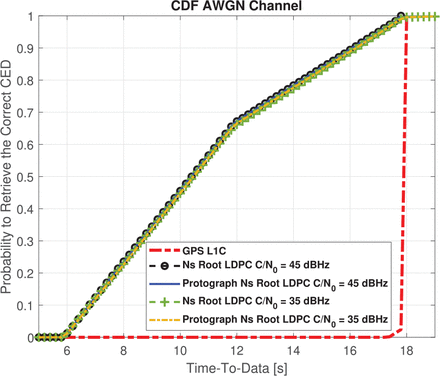
When one information block has been received, MDS permits us to retrieve information (CED) when the C / N0 is high. As a consequence, we can reduce the TTD when compared with the structure provided by the GPS L1C subframe 2 because we do not have to wait to receive all available data. This is illustrated in Figure 8, where the TTD values for an AWGN scenario with C / N0 = 45 dBHz are provided. To obtain the TTD value, the time to retrieve the CED can be obtained from the cumulative distribution function (CDF) defined as shown in Equation (7):
 7
7
where x describes the percentage confidence needed to represent the time needed by the receiver to retrieve CED. For simulations, we evaluate 100,000-times the duration needed by one receiver to obtain an error free CED. As expected, the first epoch (first synchronized bit) can arrive at any time. Following the CED structure of GPS L1C subframe 2 and the navigation message structure defined in Section 3.2, each message represents 1800 bits. Therefore, in order to initialize the first epoch value for each of the 100,000 simulations, a uniform distribution with values between 1 and 1800 was used. Each of the values represents a possible first synchronized bit. Simulation results in Figure 8 show a reduction in TTD of more than 30% for at least 66% of the time compared to the current GPS L1C signal and an associated reduction of 50% for TTD at least 30% of the time in the case of the nested Root-LDPC scheme (with a C / N0 = 45 dBHz channel conditions). The TTD reduction can be explained by the fact that when one block of information is received correctly, the demodulation algorithm is capable of retrieving the 400 missing CED bits. In other words, when 600 bits from the navigation message are received, there is a non-zero probability that they correspond to the bits of a block of information (200 CED bits and 400 redundancy bits). Therefore the demodulation algorithm can retrieve the 400 missing CED bits. Note that having received 600 + x bits with sufficient C / N0 increases the probability of retrieving at least one block of information; this enables it to retrieve the missing CED bits. In Figure 8, TTD curves when the C / N0 = 35 dBHz, i.e., standard operating point for the GPS L1C data signal as shown previously (Das et al., 2020; Medina et al., 2020)) are illustrated. Once again, we observed a reduction in the TTD for the coding structures that use nested Root-LDPC codes even if the channel conditions have been degraded. This is due to the fact that once more than one block of information has been received, the data demodulation algorithm can be used to retrieve the missing CED or to correct possible errors.
CDF of the nested Root-LDPC codes over an AWGN channel with C/N0 = 45 dBHz and C / N0 = 35 dBHz
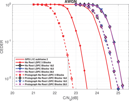
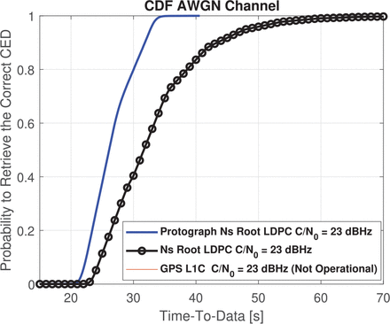
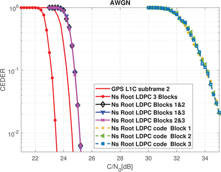
Regarding the error correction capabilities of the proposed scheme, CEDER performance of nested Root-LDPC codes shown in Figure 9 can be used when two blocks of information have been received. As shown here, we can retrieve the information (CED) with an error-correcting performance that is close to what can be achieved with the GPS L1C subframe 2 structure with only a small gap of 0.55 dBHz for an error probability of 10−2. When three information blocks have been received, the error-correcting performance is better than that provided by the GPS L1C subframe 2 at 1.2 dBHz for an error probability of 10−2. As a consequence, the receiver devices can operate in the range of C / N0 = 22 – 24 dBHz (i.e., low sensitivity). Moreover, we emphasize that protograph nested Root-LDPC codes of rate 1/3 improve the error-correcting performance by 0.25 dB for an error probability of 10−2 when 2 blocks have been received. Once the entire codeword has been received, the protograph version of the nested Root-LDPC of rate 1/3 improves by 0.7 dB for an error probability of 10−2. Of note, the GPS L1C system is not capable of operating in this range (For C / N0 ≤ 23 dBHz, the TTD is ∞) as shown in Figure 10. The findings presented in Figure 10 also reveal that higher TTD for the nested Root-LDPC codes structures because channel conditions have been degraded. However, these structures are capable of retrieving a correct CED over time because they are more resilient and can to use extra information (i.e., three information blocks) to demodulate the CED. Finally, in Figure 11, we compare the CEDER curves corresponding to a case in which one block was received compared to two or three received blocks of information for the nested Root-LDPC codes. From the information presented in Figure 11, one can verify that when one block of information is received with a C / N0 of 35 dBHz, the CEDER is of the order of 10−2. In the example illustrated in Figure 8 with C / N0 = 45 dBHz and C / N0 = 35 dBHz, the proposed navigation structure is expected to exhibit near zero failure with respect to data demodulation. This explains how the TTD can be reduced significantly when using nested Root-LDPC codes under standard open-sky channel conditions, i.e, C / N0 in the range of 35 – 45 dBHz.
CEDER of the nested and Protograph Nested Root-LDPC codes over AWGN channel
CDF of the Nested Root-LDPC codes over AWGN channel with C / N0 = 23 dBHz
CEDER over AWGN channel of a Nested Root-LDPC code of rate R = 1/3 when 1, 2 or 3 blocks are received
3.5.2 Results for Pulsed Jamming Channel
In this section, we evaluate the results of a pulsed jamming channel model. This channel assumes that a jammer device is broadcasting a Gaussian interference which disrupts some percentage P of the codeword symbols. We can model the channel scenario as follows:
We represent the transmitted message as a binary vector u = [u1, ⋯, uK ] of K bits. This message is encoded into a codeword c = [c1, ⋯, cN] of length N > K and mapped to BPSK symbols xn = μ(cn) ∈ {-1,1}. The transmission channel is modeled with an AWGN with instantaneous noise variance σ2. Moreover, some percentage P of the transmitted symbols are disrupted by an extra AWGN with instantaneous noise variance  . Then, the received symbol sequence is modeled as shown in Equation (8):
 8
8
where  and
and  are the statistical models for the noise and jamming, respectively.
  is the set of bits not affected by the jamming noise and
  is the set of bits disrupted by the jamming. Furthermore,
  denotes the cardinality of the corresponding ensemble. Finally, the channel state information (CSI) is considered at the receiver, i.e. σ2 and
  are considered known.
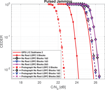
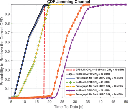
In the following simulation, P is fixed to 0.1 and the interference power Pint = 12 dB. In Figure 12, CEDER results are provided for the proposed nested Root-LDPC code and protograph nested LDPC code of rate R = 1/3. Considering the nested Root-LDPC structure, if two information blocks have been received, we can retrieve the CED with an error-correcting performance that approaches that of the GPS L1C subframe 2. A gap of 0.75 dBHz for an error probability of 10−2 is observed. This gap is reduced to 0.25 dBHz for an error probability of 10−2 when considering the protograph nested Root-LDPC structure. When three information blocks have been received (shown as the red dashed curve), the error-correcting performance provided by the regular nested Root-LDPC code is better than that provided by the GPS L1C subframe 2 by almost 1.6 dBHz for an error probability of 10−2. The error-correcting performance is improved to 3.1 dBHz for an error probability of 10−2 when using the protograph-based irregular nested Root-LDPC code structure. Simulation results (evaluated 100, 000-times the duration needed by one receiver to obtain the error-free CED) shown Figure 13 revealed a reduction in TTD of more than 30% at least 66% of the time compared to the current GPS L1C signal and a reduction of 50% of TTD at least 30% of the time when using the nested Root-LDPC scheme (with a C / N0 = 45 dBHz channel conditions). Note that this TTD reduction can be explained by the fact that when one block of information is correctly received, the data demodulation algorithm is capable of retrieving the 400 missing CED bits. The performance of this system is degraded when C / N0 = 40 dBHz, but we can still observe a TTD reduction compared to the GPS L1C system. In addition, we emphasize that the GPS L1C system is not capable of operating in ranges with C / N0 ≤ 24 dBHz as shown in Figure 12 (i.e., the TTDs for these scenarios are equal to ∞). Finally, in Figure 13 we plotted the TTD for the nested Root-LDPC structure for a C / N0 = 24 dBHz. Note that, even if there is an incremental increase in the TTD (due to degradation of the channel conditions) these structures can retrieve a correct CED over time; they are more resilient because they can benefit from extra information to demodulate the CED.
CEDER over the pulsed jamming channel with P = 0.1 and Pint = 12dB for the Nested Root LPDC code and for the protograph nested Root-LPDC code of rate R = 1/3
CDF of the nested Root-LDPC codes over the pulsed jamming channel with P = 0.1 and Pint = 12dB for C / N0 = 45 dBHz, C / N0 = 40 dBHz and C / N0 = 24 dBHz
3.5.3 Results for Urban Channels
We used a two-state Prieto model (Prieto-Cerdeira et al., 2010) to represent an urban environment with a vehicle speed of 40 km/h and an elevation angle of 40 degrees. This model considers the fading gain, denoted as hn. We represented the transmitted message as a binary vector u = [u1, ⋯, uK] of K bits. Using a binary error correcting code of rate R = K / N, the message is then encoded into a binary codeword c = [c1, ⋯, cN] of length N > K and mapped to BPSK symbols xn = μ(cn) = 1 – 2.cn ∈ {-1, 1}, ∀n = 1⋯N. The transmission channel was modeled as an uncorrelated fading channel with additional real-value AWGN with noise variance σ2, and the received symbol sequence was then s shown in Equation (9):
 9
9
where both wn and hn are identically and independently distributed random variables  and hn ~ p(h), respectively. p(h) is defined following the two-state Prieto model (Prieto-Cerdeira et al., 2010).
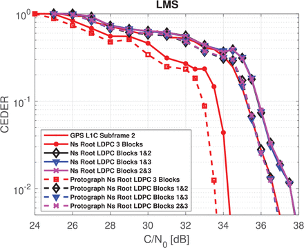
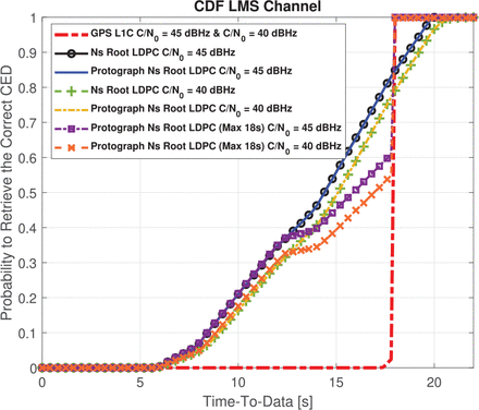
In Figure 14, the results for a regular nested Root-LDPC code of rate 1/3 are given. The values hn and σ2 are considered known at the receiver. Considering the nested Root-LDPC code, when two information blocks have been received, we can retrieve the information (CED) with an error-correcting performance that approaches that of the GPS L1C subframe 2. With nested Root-LDPC codes and and three received information blocks, the error-correcting performance is better than that provided by the GPS L1C subframe 2 by almost 2.5 dBHz for an error probability of 10−2. The error-correcting capability was improved to 3.2 dBHz for an error probability of 10−2 when using the protograph-based irregular nested Root-LDPC structure. Simulation results (evaluated 100, 000-times the duration needed by the receiver to obtain the error free CED) shown in Figure 15 reveal a reduction in the TTD of at least 80% compared to the TTD of the GPS L1C signal when nested Root-LDPC schemes are used (i.e., when the C / N0 = {40,45} dBHz). The reductions in the TTD can be explained as follows: when more than one block of information is received, the data demodulation algorithm can be computed in an attempt to retrieve the 400 missing CED bits. However, unlike running the demodulation algorithm on the AWGN channel with high C / N0, data is received over the land mobile satellite (LMS) channel may require more than one block of information even if the C / N0 is high. This is because the LMS channel is a non-ergodic channel; fading events can reduce the instantaneous SNR for a particular set of received symbols. Given the navigation structure presented in Figure 15, if two blocks of information are required to retrieve the CED without error, around the TTD of the proposed structure is higher than the TTD of the GPS L1C system approximately 20% of the time. This particular case may occur if the receiver begins to receive data at the end of the first information block. Once the second block is received, it is likely that, because of the nature of the LMS channel the demodulation algorithm will not be capable of correcting the errors. It will likely be necessary to wait until the third block of information has been received, which will result in a higher TTD with respect to the GPS L1C structure. One possible solution to avoid exceeding the TTD of the GPS system is to enforce the data demodulation once 18 seconds of message have been received. The TTD curves for this particular structure have also been included in Figure 15 when the C / N0 = {40,45} dBHz. Note that under these particular conditions, the TTD of the proposed scheme will not exceed that of the GPS L1C system.
CEDER over an urban channel using nested Root-LPDC code and the protograph nested Root-LPDC code of rate R = 1/3
CDF of the nested Root-LDPC codes over an urban channel with C/N0 = 45 dBHz and C / N0 = 40 dBHz
Finally, we highlight the fact that because these error-correcting schemes can drastically reduce the demodulation threshold without increasing the TTD, the data can be demodulated using new system operations points (i.e., those allowing both (i) data demodulation in situations in which standard channel coding families cannot function, and (ii) a reduction of the TTD in harsh environments). Demodulation performance can be improved by constructing nested Root-LDPC families with lower rates. However, the data demodulation with a channel decoder using a lower rate implies an increase in the receiver complexity. The complexity/performance trade-off is beyond the scope of this paper.
3.5.4 Effect of the CED Size
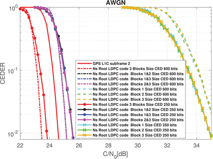
Because these codes can be applied to any new GNSS signal, we compared the error- correcting performance of nested Root-LDPC codes for two different CED sizes. Thus, in Figure 16, we illustrate the CEDER for a nested Root-LDPC code of rate R = 1/3 based on a CED size of 600bits (i.e., the CED size of the GPS L1C) and a reduced version of the Galileo CED (Anghileri et al., 2012). This reduced version of the CED is intended for use in future releases of Galileo (Paonni & Bavaro, 2013). The CED information block has 250 bits. Note that reducing the size of the data will have a direct impact of the error-correcting performance (Richardson et al., 2001). Then, considering the AWGN channel when only one block has been received, the reduced CED size results in better CEDER. However, when two or three information blocks are received, lower CED size results in deterioration of the CEDER.
CEDER over an AWGN channel with two different CED sizes. Nested Root-LDPC code of rate R = 1/3 was used as a channel coding scheme
4 CONCLUSION
In this paper, we present a method that can be used to design error-correcting schemes for GNSS systems that can provide MDS and full diversity as well as inherent rate adaptation depending on the number of information blocks received. This is known as a nested code property. The first property permits the receiver to reduce the TTD in straightforward environments; the CED can be retrieved based on the receipt of k information blocks. Moreover, based on full diversity and the nested code, enhanced error-correcting performance and an improved data demodulation threshold can be achieved. Given the improvements in data demodulation, these structures lead to a reduction in the TTD under harsh environmental conditions including those with low carrier to noise ratios and pulsed jamming as well as standard urban environments. The outcomes associated with use of the proposed error-correcting structures are then compared with those resulting from the GPS L1C subframe 2. Simulations document a significant improvement in the error-correcting performance when three information blocks are received:
Under an AWGN environment when three information blocks are received, an enhancement of the error-correcting performance of 1.2 and 1.9 dBHz can be achieved using regular nested Root-LDPC codes and protograph-based irregular nested Root-LDPC codes, respectively. Moreover, the results of simulations reveal reductions in TTD of more than 30% for at least 66% of the time compared to those of the current GPS L1C signal, with reductions in TTD of 50% at least 30% of the time when using the nested Root-LDPC scheme for standard channel conditions (i.e., the C / N0 in the range of 35 to 45 dBHz). Finally, in contrast to the GPS L1C structure, the proposed message structure can be operational in the range of C / N0 = 22 – 24 dBHz.
In a pulsed-jamming environment when three information blocks have been received, the error-correcting performance can achieve increases as high as 1.6 and 3.1 dBHz when using regular nested Root-LDPC codes and protograph-based irregular nested Root-LDPC codes, respectively. Moreover, simulation results also reveal a reduction in the TTD of more than 30% for at least 66% of the time compared to the current GPS L1C signal and an associated TTD reduction of 50% at least 30% of the time when C / N0 = 45 dBHz. In addition, when channel conditions are degraded, the proposed structure can be used to reduce the TTD and thus improve the operational range.
When three information blocks are retrieved in an urban environment, error-correcting performances of 2.5 / 3.2 dBHz are achieved using regular nested Root-LDPC codes and irregular protograph nested Root-LDPC codes, respectively. Moreover, simulation results revealed a reduction of TTD for at least 80% of the time compared to the current GPS L1C signal when C / N0 = {40,45} dBHz. For the other 20% of the cases, use of the GPS L1C structure results in a diminished TTD. To improve the TTD time, the message can undergo forced demodulated once 18 seconds of information have been received. Under this configuration, the TTD from the nested-root LDPC structure will always be lower or equal to the TTD of the GPS L1C system.
HOW TO CITE THIS ARTICLE
Ortega, L., & Poulliat, C. (2023) Global navigation satellite system channel coding structures for rapid signal acquisition in harsh environmental conditions. NAVIGATION, 70(3). https://doi.org/10.33012/navi.585
CONFLICT OF INTEREST
The authors declare no conflicts of interests.
ACKNOWLEDGMENT
Part of this work was presented earlier at the ION GNSS+ 2019 conference (Ortega et al., 2019). This work is part of a doctoral dissertation (Ortega, 2019).
This is an open access article under the terms of the Creative Commons Attribution License, which permits use, distribution and reproduction in any medium, provided the original work is properly cited.


